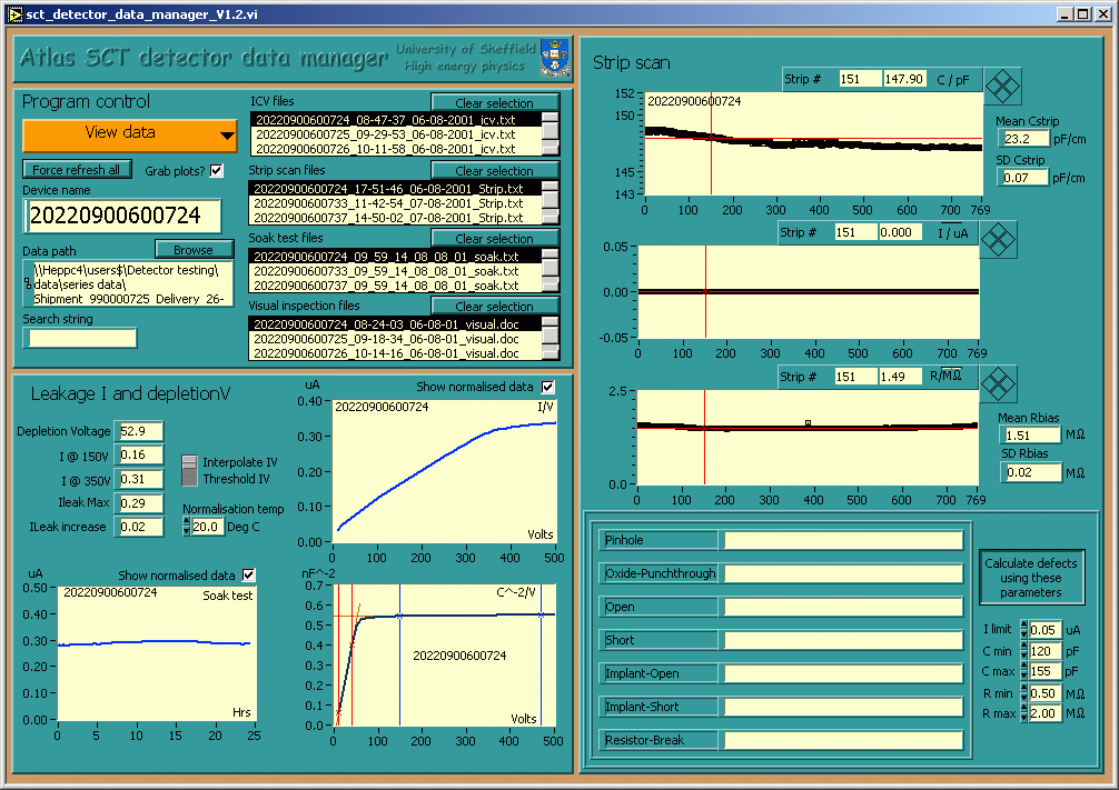
Using the SCT database upload application
The main program "sct_detector_data_manager_Vx.x.vi"
User interface

Program controls
Action control
This is a menu ring control that appears at the top left of the Program controls section. The main functions of the program are available through this control:
View data, this is the default action and just displays the data currently loaded.
Next device, Loads the data from all available files in the search path directory belonging to the device which has the closest Atlas serial number after the current device.
Previous device, Loads the data from all available files in the search path directory belonging to the device which has the closest Atlas serial number before the current device.
Upload to SCTDB, Uploads the data for the current device to the database. Click here to find out more about this.
Generate paperwork, Generates a set of paperwork for the current device. Click here to find out more about this.
Configuration, Opens a configuration dialog - enabling the user to enter information specific to their setup. Click here to find out more about this.
Exit, Leave the program and save your settings.
Search path
Enter the path of the directory containing the files you want to look at here. A dialog is generated if you leave this blank or enter a path which is not valid.
Search string
Enter the atlas serial number of the detector here or any other part of the filenames you wish to look at. If you leave this box empty all files will be listed. You can use wildcards here.
Listboxes "*** files"
There are four of these boxes in which the available filenames are displayed. To clear the list box selection just press the appropriate Clear selection button. For routine work it is best to restrict the displayed files to those from a single detector. Do this by using the atlas serial number as the search string.
Force refresh all
This button makes everything on the front panel reload and recalculate. This is usefull if the data files have changed on disc or just to make sure.
Leakage I and Depletion V
This section displays IV, CV and soak test data. Checking the Show normalised data boxes causes that data to be replaced with data normalised to the temperature chosen in the Normalisation temperature control. There are four cursors on the CV plot, these are used to define the start and finish points of two least squares fit lines. The left hand pair of cursors should be red and the right hand pair blue. Adjust the cursors so that fits are taken over the two linear regions of the plot. The depletion voltage is taken as the point where the two lines intersect. The Interpolate / Threshold control defines the technique used to extract the current at 150 and 350 volts from the IV data.
Strip Scan
This section displays the strip scan data. Defective strips are identified using the values entered in the controls to the right of the defect lists. The defect list can be edited manually after the file has been loaded and the Enter defects manually or Calculate defects using these parameters button has been changed as required. Changing the state of the Enter defects manually or Calculate defects using these parameters button will overwrite any previous entries you have made into the defect list. This may seem daft but it works quite well in practice. Defects should be entered as integers seperated by commas. Where defects exist on a string of consecutive strips this can be entered by putting a tilde between the first and last strips e.g. 3~48. Unfortunately the more commonly used notation using the - symbol confuses Excel. It is hoped that interacive error checking of the defect data will be incorporated in the future. In the mean time please take great care not to make mistakes here.