

Light Injection and Calibration
(Matt Lawe, Jon Perkin, Leon Pickard, Lee Thompson, Callum Wilkinson)
|
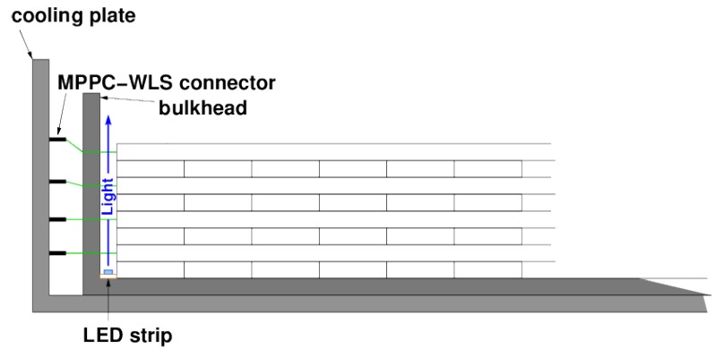
| Schematic layout of the ECal LI system, showing the end of a module with the layers of scintillator bars, the LED strip and the wavelength-shifting fibres. |
The ND280 ECal Light Injection System
The ECal light injection system consists of a series of strips of blue LEDs mounted between the scintillator layers and the outer bulkhead of each ECal module, as shown in the diagram above. The LEDs can be flashed in very short pulses, providing "proof-of-life" and also timing calibration for the ECal MPPCs. This system was designed and built in Sheffield after it was decided, late in the ECal construction phase, that such a system was necessary. As it was retrofitted to an existing design, the system had to fit into a very tight space and be constructed on a short timescale. Nevertheless, all the systems work effectively, except for the system on the downstream ECal, which may have been damaged during assembly.
The LI system can be run interspersed with beam data, to provide continuous monitoring of the health of the ECal. In this mode, it can in principle be used for the rapid detection of RMM timeslips (see below), although the fact that the ECal timing is usually referred to the DsECal, where there is no working LI system, presents a technical problem.
LI: the movie— click here to see an animation of LI data.
The LED strips of the LI can be flashed face by face instead of all at once. Flashing one face and reading out the MPPCs at the other end of double-ended bars provides a clean method of measuring the speed of light transmission down the WLS fibres. Subtracting the near-side time from the far-side time cancels out any delays introduced by the electronics, and repeating the process with the illumination coming from the other side and averaging the two results cancels any electronic offsets between the two ends.
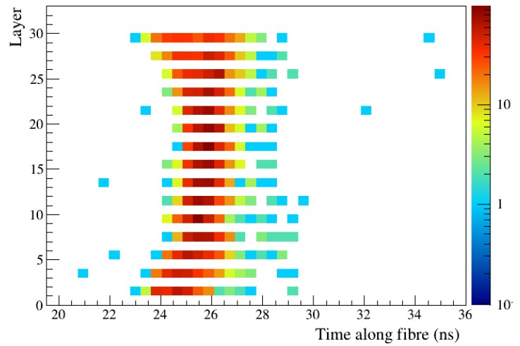
|
| Light transmission time down bar against layer number (bars in alternate layers run orthogonally and were not illuminated). |
The results show that the light transmission time down the bars can be measured to an accuracy of a few percent. There is a slight but consistent variation with layer number, which is yet to be understood.
Timeslips
The ND280 DAQ is synchronised to a master clock. However, when units are power cycled, the resynchronisation of slave clocks to the master sometimes jumps by 10 ns (four clock ticks). These so-called "timeslips" can occur at several different levels in the master-slave hierarchy. When they affect the whole detector, they are obviously not serious, but timeslips which affect only single subdetectors or parts of subdetectors must be detected and corrected for during calibration so that hit times across the whole detector can be compared during reconstruction.
Identification of timeslips was originally done manually by scanning the timing data. It is not difficult for the human eye to pick up timeslips, but it is tedious. As part of the "service work" of their PhDs, Matt Lawe and Leon Pickard successively took on this task, and developed algorithms to identify timeslips automatically. The output from the algorithm can be seen in the left-hand panel below.
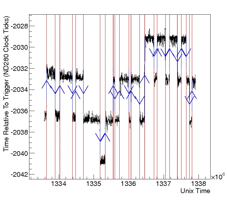
|
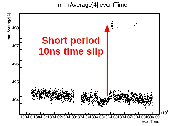
|
| Timeslips in ECal RMM11 (known for its instability: most RMMs experience far fewer timeslips than this). The blue arrows mark the slips. | A short-duration timeslip in an LI test run. Note the much finer timescale (running from 1384.30 to 1384.39). A timeslip this short would probably be missed by the standard monitoring. |
As shown in the right-hand panel above, the LI system has the potential to find even very short timeslips with high efficiency during interleaved running. The only difficulty is that the reference ECal module, the DsECal, does not have a working LI system, making it difficult to combine LI results with the rest of the calibration software.