Drawings & Photos
IMPORTANT NOTE: These drawings are not necessarily up-to-date neither is this a complete list and
under no circumstances should they be used as a general drawing repository.
Some of these drawings illustrate simplified geometry that was specifically intended for the magnetic model.
They have been provided for the sole purpose of being able to reference the source of the model's geometry.
All other drawing queries must be directed through Jason Tarrant.
Amplifier Sketches
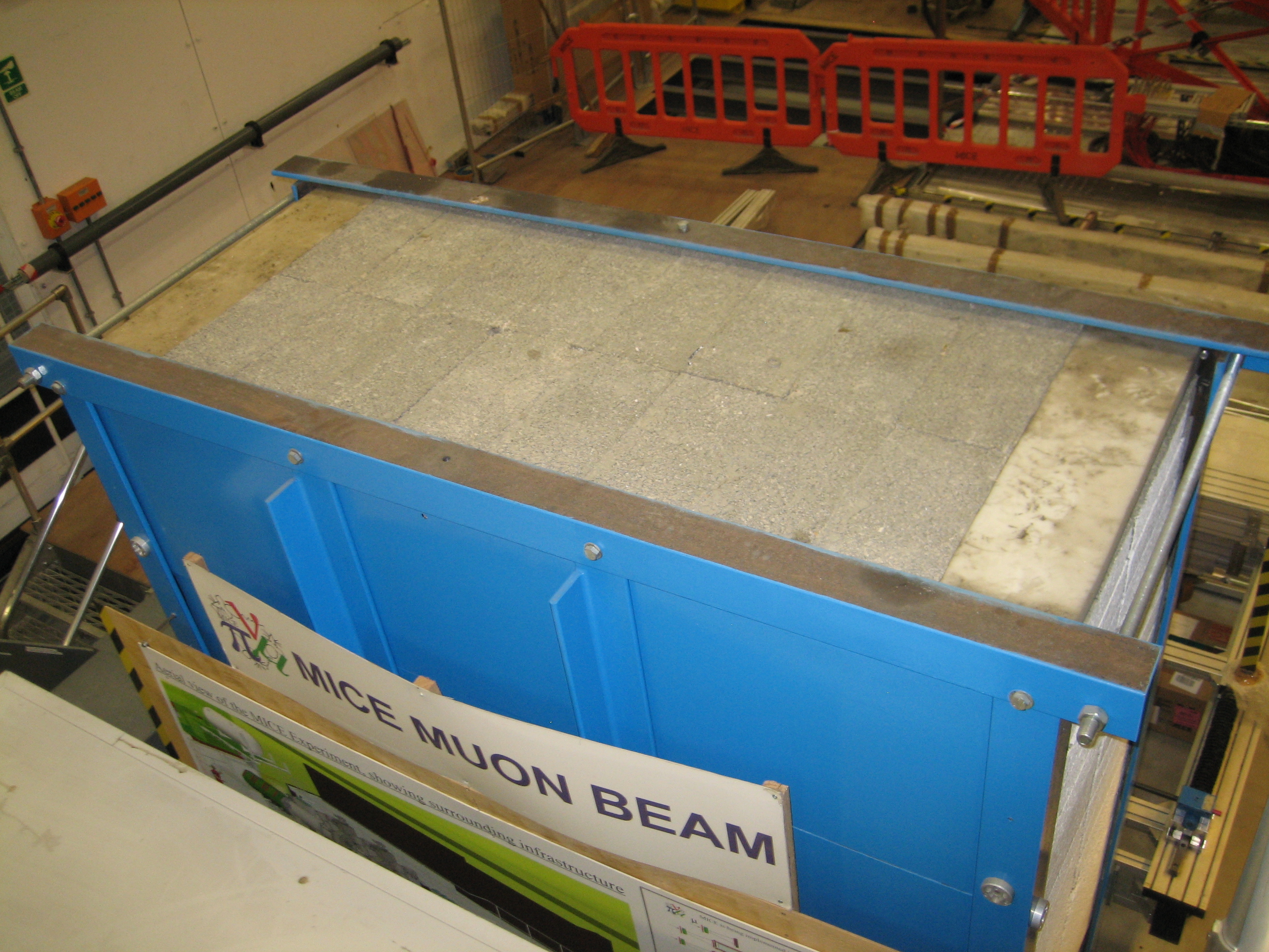
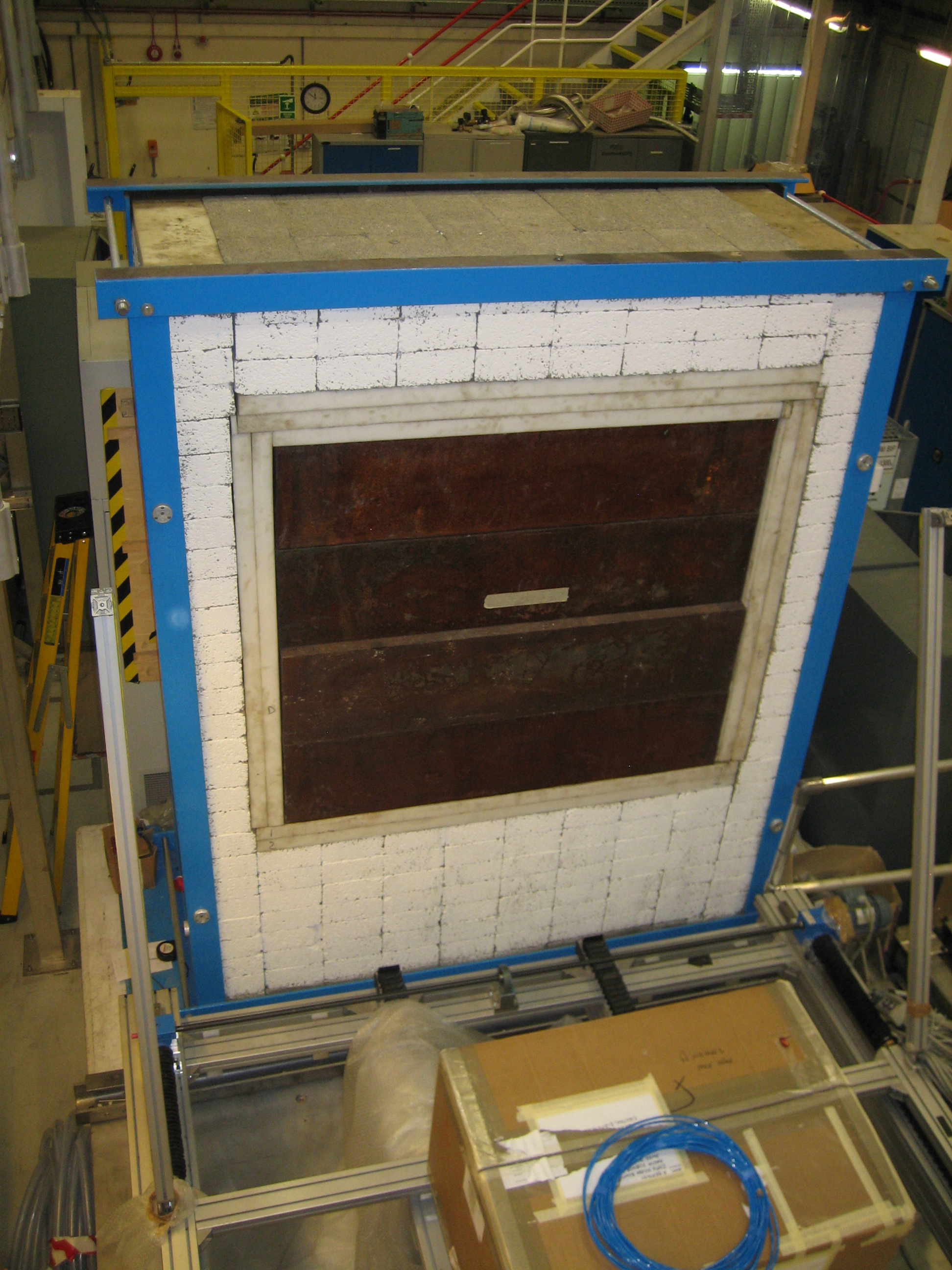
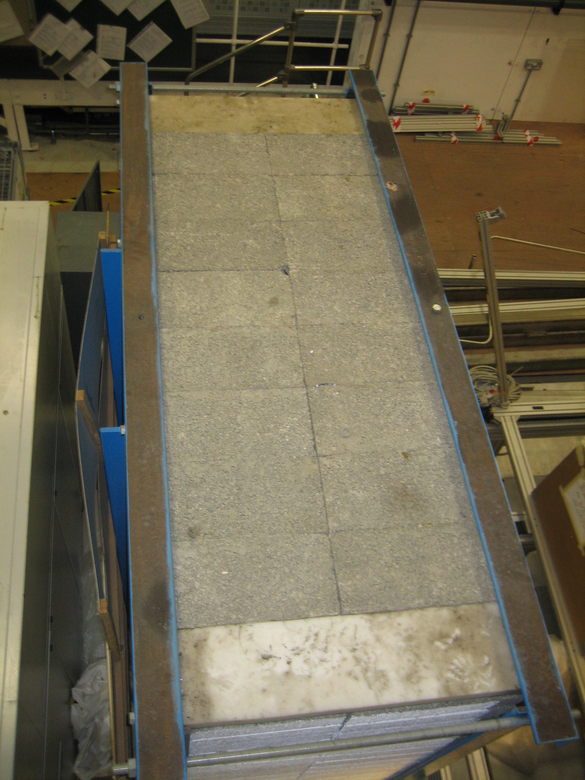
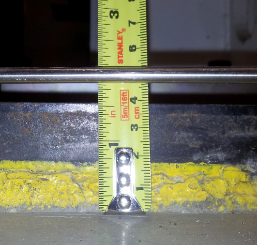
BeamDump - TD-1055-161
Buried Magnet Bases - DR-3032-004
Crane Drawing 1
Crane Drawing 2
Dipole D2 - TD-1152-9345
DSA Steel - TD-1189-1186
KL & EMR Assembly - TD-1152-9075
EMR Plate
MICE Experiment - Essential Geometry 1 - TD-1189-1143
MICE Experiment - Essential Geometry 2 - TD-1152-9507
MICE Experiment - Essential Geometry 3 - TD-1189-4000
North Mezzanine - TD-1189-1235
North Mezzanine - TD-1189-1235-1
North Shield Wall/South Shield Wall - TD-1189-1159
Plant Room Proposal - TD-1189-9061
Plant Room Proposal - Ref to MICE Hall - TD-1189-9062
Quadrupoles - TD-1152-9313
Quadrupole Bases - TD-1189-1239
Racks behind the North Shield Wall
Mass of a standard Rack i.e. behind the North Shield Wall - J. Webb
South Shield Wall - TD-1189-1016
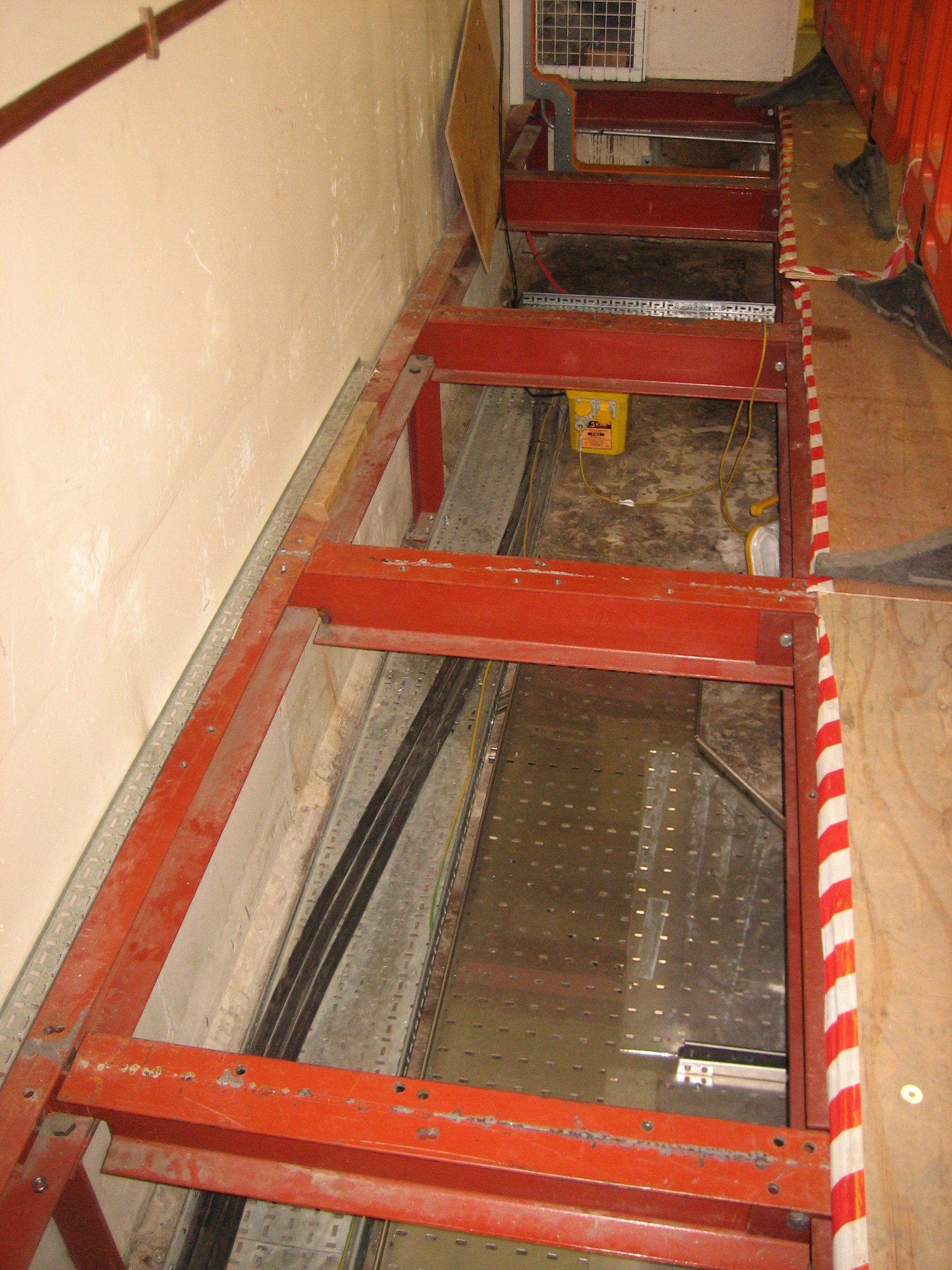
Trench & Cellar - TD-1189-1014
Virostek Plates - TD-1189-1167
Walls - MICE Hall TD-1189-1010
Walls around MCR area - TD-1189-1288
South Side Buildings 1 - Rack Room 2 Details - TD-1189-1277
South Side Buildings 2 - Include Location of ISIS MCR - TD-1189-1284
South Side Buildings 3 (MLCR/PR/RR etc) - TD-1189-1288
South Side Buildings 4 (MLCR/PR/RR etc) - TD-1189-1289
Entrance MICE HALL to SSB - TD-1189-1351
Shield Wall - Details of I beam and plate sections.
Location of Compressors against the West Wall - TD-1189-4018
Reference Location of Virostek Plates for Step IV - TD-1189-1905
PRY 1 - DRAFT DRAWINGS ONLY!! TD-1189-1785
PRY 2 - DRAFT DRAWINGS ONLY!!
Sub-Station/Rack Drawings - June 2013
Equipment Locations
Rack Dimensions and Weights
Sub-Station Dimensions and Weights(Old Masses)
Other Sub-Station Dimensions
Other Sub-Station Dimensions 2 (Revised Masses)
Trench Transformer Dimensions and weight.
Note: The Sub-Station panel wall thickness can be taken to be 2mm.
Model/CAD geometry checks
TD-1189-1185 - CAD/Model Geometry Check 1
Overlay_09_10_12 - CAD/Model Geometry Check 2 - 9th October 2012
Photos
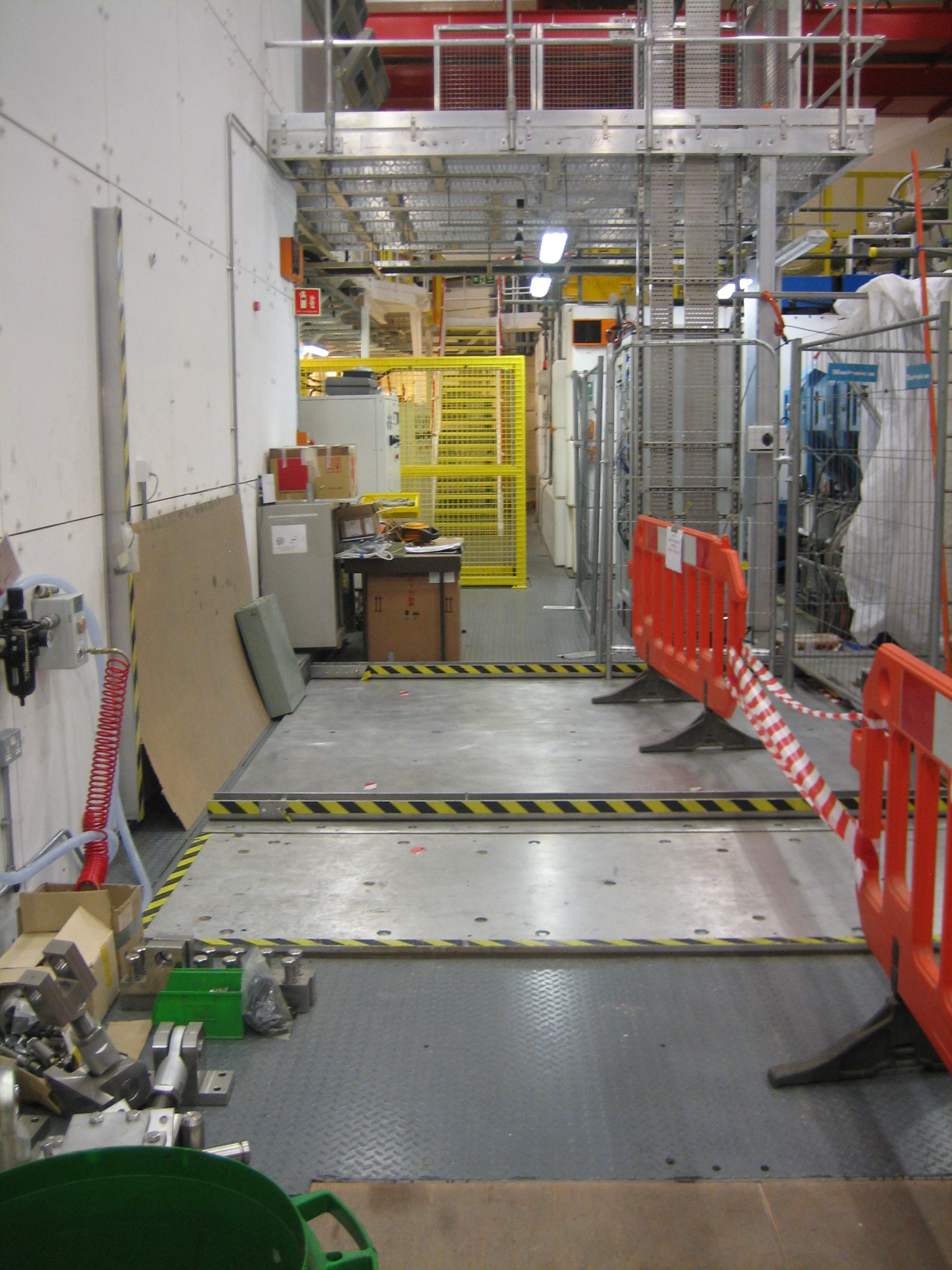
MICE Hall Service Photos July 2012
BeamDump Photo 1
BeamDump Photo 2
BeamDump Photo 3
BeamDump Photo 4
BeamDump Photo 5
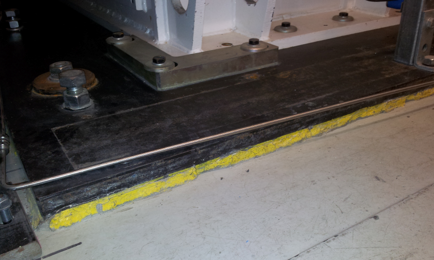
Quad Baseplate Photo 1
Quad Baseplate Photo 2
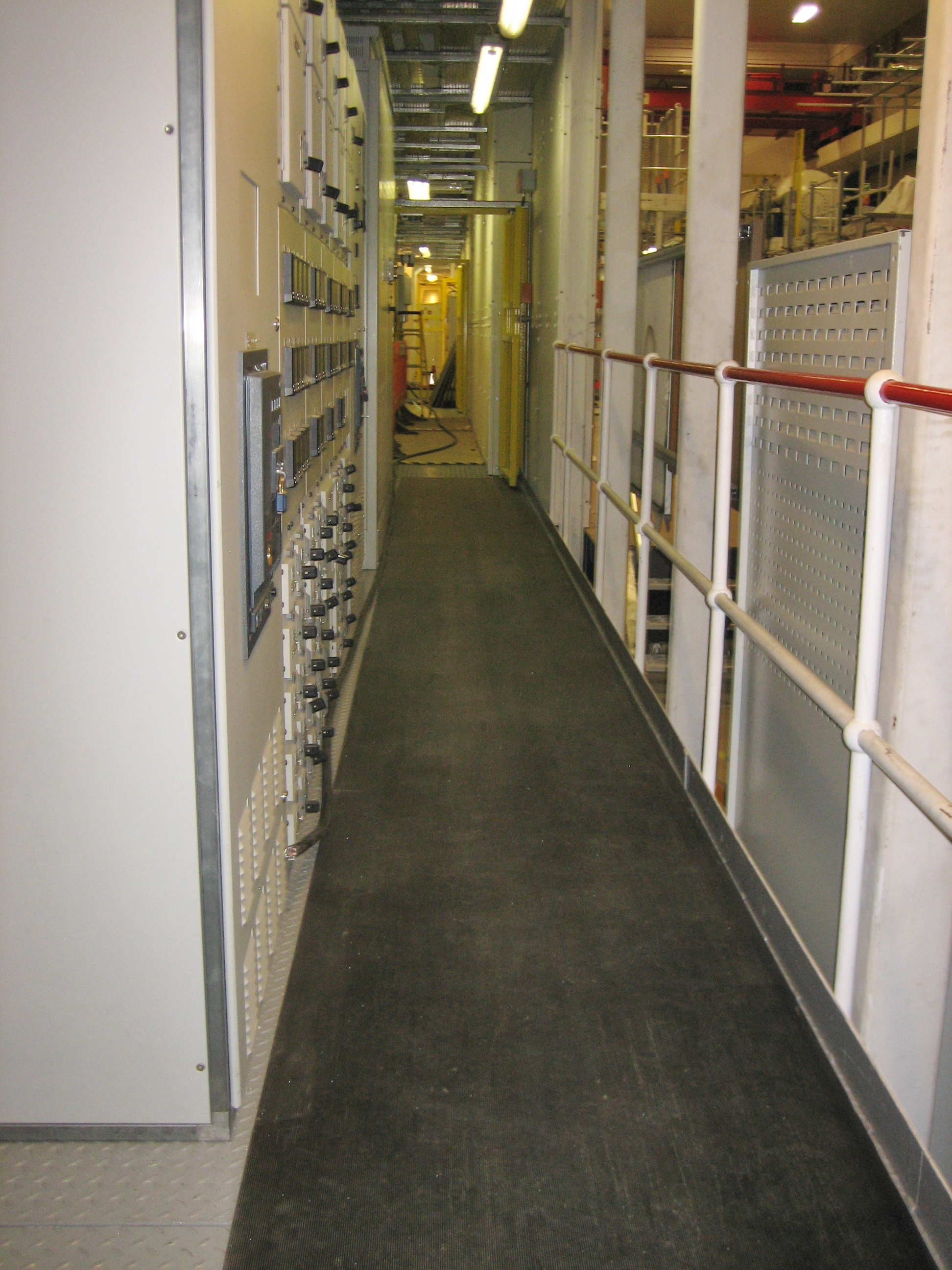
Behind North Shield Wall Photo 1
Behind North Shield Wall Photo 2
Behind North Shield Wall Photo 3
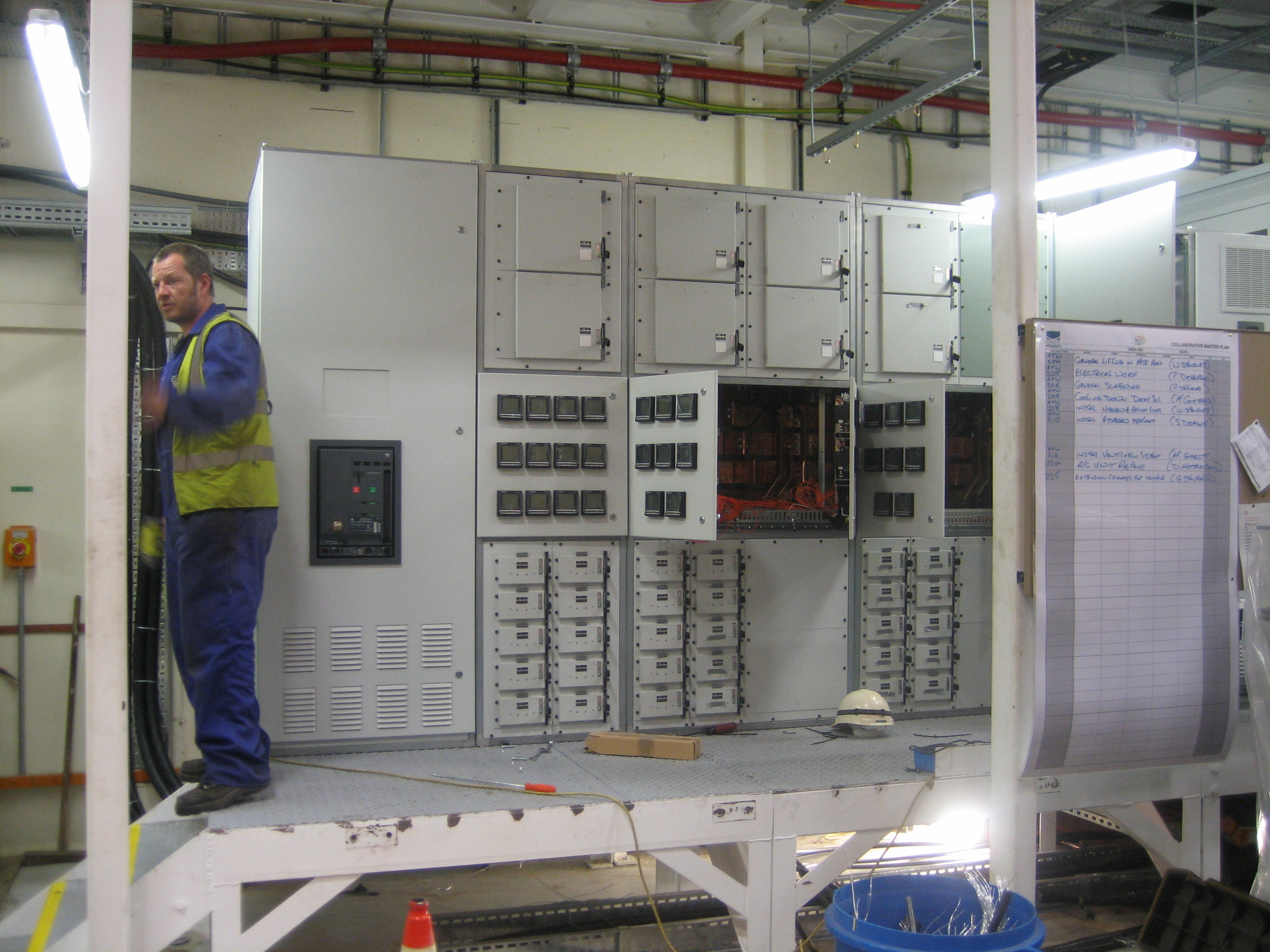
Sub-station