ATLAS SCT End-Cap Assembly Model
>> ATLAS home page >> Picture gallery
Introduction
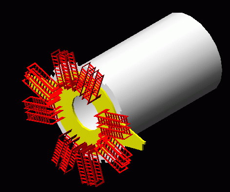
In order to assess the practicalities of installing services to the forward region end cap, a full size model representing 105 degrees of the end cap has been produced at Sheffield. The model includes removeable disks with simulated PPF0 panels. The main use of this model is to experiment with the layout and connection of the services over the surface of the end cap support cylinder. Kapton power tapes, optical cables and cooling pipes and their connections will be modelled and assembly methods investigated. All the necessary parts are modelled in wood, cardboard or plastic.
Autocad model
 Click here to
download the model
Click here to
download the modelProgress reports:
Service feedthrough developments 5-Oct-03
The design of the service feedthrough has brought up several new problems:
The current understanding is that the services will feed through the thermal enclosure wall supported by racks on the inside. In the case of the PPF1 the feedthrough occurs at the TI, which is awkwardly short, and the cable run is offered from the inside of the thermal enclosure. The arguments below reverse this setup with the service support racks on the outside of the thermal enclosure and the services being fed into the thermal enclosure from the outside. This arrangement simplifies the use of the space between the endcap and the wall of the thermal enclosure and addresses the short TI, cable handling and mounting of the support wing.
Icing and condensation around the feedthroughs in the thermal enclosure could
become a major problem. Ideally we would like to see a step in temperature from
-7 DegC to ambient at the feedthrough. To get as close as possible to this ideal
we need to chose the part of the service run with the lowest thermal
conductivity to pass through the feedthrough. We also need to make a good seal
around the feedthrough. In the case of the PPF1 the low mass tape itself seems
the best candidate to pass through the feedthrough, leaving PPF1, TI & TPP
outside the thermal enclosure. With this
arrangement there is no reason why the excess LMT, PPF1, TI & TPP cannot be
mounted in the same box reducing the risk of connection errors and damage. The
racks used to support the PPF1 boxes would also be mounted outside the thermal
enclosure allowing better access. In order to further reduce condensation the
whole area containing the
PPF1 box racks can be enclosed, this enclosure will fill with dry purge gas from
the main enclosure leaking through the feedthroughs. This "thermal buffer zone"
can also incorporate cable tidying & support. The buffer zone can be either
constructed within the thermal enclosure or on the outside. The two
arrangements are shown in the pictures below.

Model showing feedthrough thermal buffer zone inside the thermal enclosure

Model showing feedthrough thermal buffer zone outside the thermal enclosure
Colour scheme:
Light blue = foam insulation
Yellow = Support wing
Blue = Kapton LMT
Red = PPF1 box frame and cable supports
Grey = Endcap and PPF1 boxes.
The light blue square edged panel represents the outside wall of the thermal enclosure
Having this thermal buffer zone inside the thermal enclosure allows
easy transport without disturbing the PPF1 boxes and the cable tidys to remain
in place while the covers are removed for access but will reduce the room
inside the thermal enclosure. Having the thermal buffer zone outside the
thermal enclosure leaves maximum room at the front of the endcap but encroaches
on the 1m free space outside the thermal enclosure available at Nikhef and may
make access for other work impossible after the cables are connected.
The design of the TPP is not yet established and is crucial to the design of the PPF1 box.
The effect of the full complement of services entering the thermal enclosure needs to be understood and design of the cable routing will be vital if there is to be adequate access.
The LMTs can now be held within the thermal enclosure such that the stub-wing can be removed and endcap support wing mounted.
Feedthrough detail
The picture below shows the proposed LMT feedthrough with bungs to the right
hand side removed. The bungs consist of an insulating foam plug with locating
lip and soft foam sealing face (in yellow). The bungs are shown removed from
their holes in a section of thermal enclosure wall (in light blue) and are
fitted from the inside of the thermal enclosure.

Detail of LMT feedthrough
Colour scheme:
Light blue = foam insulation
Yellow = Soft foam gasket
Blue = Kapton LMT
Red = PPF1 box frame
Grey = PPF1 boxes
PPF1 temporary support mount 13-May-03
A model of the support structure to mount PPF1 to the temporary patch panels was constructed with the PPF1 boards in the vertical plane. It was found that the lengths of the low mas tapes caused them to form a stressed bunch that would damage them. We have now moved to a structure that holds the PPF1 boards horizontally and this will allow the tapes to coil more easily while still allowing good access to PPF1. This support can be adapted to suit the different assembly configurations at Liverpool and Nikef and can also be adapted to allow access for the rear wing assembly. See the gallery for pictures of both supports.
Notes on Assembly meeting at Sheffield 28-Feb-03
Present: CMB, TJ, JT, BK Current status:Ben has set-up the disks in the mock-up with cardboard connectors and has 'glue-on' clips that go on the end of the mock-LMTs.
The model currently has one quadrant of the LMT PPF0s populated on every disk.
To-do:
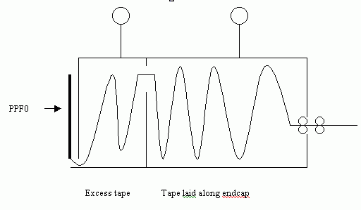
The LMT tapes can be laid out along the endcap using a tape box. The LMTs can be neatly spooled in the box, with PPF1 attached at one end and the PPF0 connector at the other end. This allows the connectors to be accessed for testing. The box can also be used to store the excess tape and provide a mount for PPF1 once the tapes are laid out along the cylinder. The optimum design of the box may therefore consist of two compartments with the LMT length along the endcap in one compartment and the excess length that needs to be stored during transport in another compartment.

Sketch of tape dispensing box
The tapes are dispensed through rollers and this prevents the tape from feeding back into the box and causing eg a jam, and ensures the tape is flat.The tape box with slung from a rail or wire during assembly. This will remove the problem of having to handle large bunches of cable during assembly and reduce the risk of items falling onto the endcap.
To-Do:
Strain relief for tapes:
Put guttering on surface of endcap to guide tapes, and prevent them from falling down the side of the endcap. There will be straps to tie down tapes just before the apertures. This will isolate the point where the tape makes connection with PPF0 from the rest of the tape to prevent any problems with other tapes interfering.
To-Do:
Tape lengths and losing excess tape Need to be able to 'lose' excess tape. The area between the solenoid and the TRT can no-longer be used due to the position of A-frames in the squirrel-cage. This may be done in the service feed through between the TRT endcap and TRT-C.
To-Do: